ATtiny13 Dice
 I wanted to learn how to get the handful of non-Arduino AVR chips I have working. I wanted to learn the basics of the C API, the development toolchain, and get a sense for what can be done with the little ATtiny microprocessors. Starting with the most limited, teeny tiny little chip (the 1k ATtiny13), I made a dice.
Parts
Before starting, I had a handful of tools and parts. In addition to the bits I had in my kit already, I ordered some parts from the super-helpful folks at Sparkfun.
Atmel AVR ATtiny13 (Sparkfun, $1.94)
AVR programming adapter (Sparkfun, $0.95) Not strictly necessary but add some header pins and it makes prototyping this stuff much easier
Sparkfun’s AVR Pocket Programmer (Sparkfun, $14.95)
A momentary contact push-button switch
Some LEDs
A couple of 10k resistors
Software Setup and Reference
The Pocket Programmer product page at Sparkfun has some helpful links and comments for the newb. I downloaded the Windows USB driver from there.
WinAVR is the obvious choice as a programming toolchain. I downloaded and installed this, and after a little time found that the Programmer’s Notepad bundled works perfectly well as a source editor. I’m still using it.
I did download and try Atmel’s AVR Studio IDE, but didn’t really use it much beyond seeing its simulator.
This was a really useful getting started guide for me, taking you through hooking up the programmer to the chip, and the very most basic steps. I won’t repeat too much of this kind of stuff – just check out that page.
The ATtiny13 datasheet and the AVR libc API docs were open the whole time too.
The Plan
I wanted to push a button and have a familiar dice display show me the result. Obviously it needs to pick a random number between 1 and 6 to display. I wanted some kind of flashy effect to take the place of the dice roll.
From playing around with charlieplexing on arduino I figured that would be a sensible way to get going with driving the LEDs. The dice will need a total of 7 LEDs, so I sketched out a charlieplexed array of 6 LEDs plus a single LED all on its own. This requires a total of 4 tri-state I/O pins.
The pushbutton switch will need an input pin, so I need 5 of the 6 available I/O pins on the chip. I used a 10k pull-up resistor (R1) on the switch input pin – when the switch is pressed it pulls the pin low, and it’s this state I watch for in the code.
Finally, there’s the standard pull-up resistor (R2) to keep the RESET pin high means the following circuit:

Nothing too fancy. Right now I’m just drawing +5V from the USB programmer – later steps will include adding power to the circuit.
Coding and Testing
Even the simplest source needs a way to be compiled, then programmed onto the chip. Helpfully, WinAVR comes with a template makefile in the sample directory. There were a couple of customizations to this basic template:
MCU = attiny13
F_CPU = 1200000
AVRDUDE_PROGRAMMER = usbtiny
The build targets in the makefile correspond with the tools menu items in Programmer’s Notepad – Make All, Make Clean and Program.
As far as writing the code, the most helpful resources were the API docs, and the AVR Freaks forum.
When it came to testing the code on the device, I initially ran into a problem with the programmer being unable to connect to the target – a rc=-1 type error. It turns out that having the chip in the circuit was messing with the programmer. By disconnecting the MISO, MOSI and SCK pins from the LEDs (these pins also function as PORTB bits) the programmer worked fine. This is something I need to fix in the future – unplugging 3 wires to program the chip then plugging them back in gets pretty tired…
Results
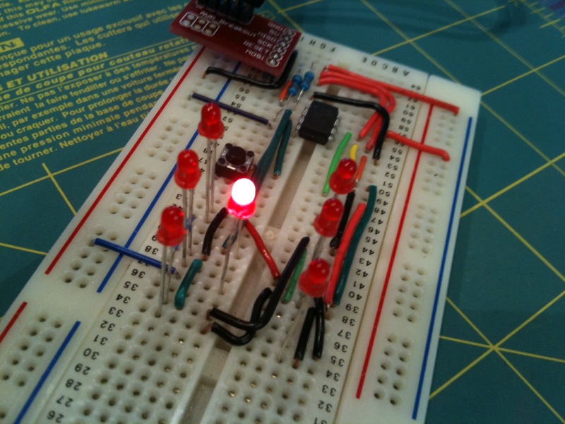
Here’s a pic of the breadboard circuit. You can see the programming adapter plugged in at the top left of the board.
Download the Source Code
Next Steps
I’m going to add battery power and a regulator to the circuit, build it on proto board, and enclose it. There’s a little tweaking of code required, and I’d like to squeeze a better “roll” effect in (but I’m pretty full up on program space already).
